Bolted flange joint FEA and leakage analysis
A bolted flange seals only if the gasket keeps enough contact stress all the way round, through bolt-up, pressure, temperature and external loads. The finite element model shows how that stress is distributed and whether the flange, bolts and gasket stay within their limits.
When you need it
- A joint leaks after bolt-up, at start-up or during thermal cycles.
- A non-standard flange, a large diameter or a high-pressure joint needs design by analysis.
- External bending moments from the piping exceed what a standard flange check covers.
- The bolt-up procedure, gasket type or bolt material is being changed.
What the analysis covers
- Bolt preload and its scatter from the tightening method, applied bolt by bolt.
- Gasket contact stress around the circumference, with non-linear gasket loading and unloading behaviour.
- Flange rotation, bolt bending and load changes through pressure, temperature and external moments.
- Stress linearisation and classification to ASME BPVC Section VIII Division 2 Part 5.
- Comparison with the ASME BPVC Section VIII Division 1 Appendix 2 rules where they apply.
What we need from you
- Flange, gasket and bolt drawings or standard designations, with materials.
- Design and operating pressure and temperature, including transients.
- External forces and moments at the joint, typically from the piping stress analysis.
- Gasket data: type and the loading and unloading curves from the manufacturer.
- Assembly procedure: target bolt stress, tightening method and lubricant.
What you receive
- A report with assumptions, method, verification against the Appendix 2 hand calculation, and margins against the agreed criteria.
- Gasket contact stress maps and bolt load history through each load step.
- The scripted model files and a results review call.
- Where it helps, a short animation of the joint opening under load for non-specialists.
Codes and standards
- ASME PCC-1
- ASME BPVC Section VIII Division 2 Part 5
- ASME BPVC Section VIII Division 1 Appendix 2
The assessment is framed against the edition your project specifies.
Related cases
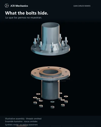
Generic, synthetic studies from the portfolio that show this kind of analysis at work.
Questions clients ask
Why does a joint leak when the total bolt load looks sufficient?
Total bolt load says nothing about how it is shared around the gasket. Uneven tightening, flange rotation, gasket relaxation and external bending leave some sectors below the stress needed to seal while others are crushed. The model shows the contact stress at each sector and load step, which is where a leak path starts.
How is the bolt preload target chosen?
It is a balance: enough to keep the gasket sealed through pressure, temperature and external loads, but not so much that the gasket, bolts or flange yield. ASME PCC-1 gives a method to select the assembly bolt stress within these limits. The target depends on the gasket, the flange and the tightening method, which also sets the scatter.
Why is stress linearisation needed?
Design by analysis in ASME BPVC Section VIII Division 2 Part 5 splits stress into membrane, bending and peak components, each with its own limit. Linearisation converts the finite element stresses through a section into those components. The result depends on where the sections are placed, so their choice is documented in the report.
Contact
Have a case like this?
Send the question and the data you can share. You will get back a proposed scope, method and timeline.
Confidential by default: project data is never used in public material.